HCM(YL)
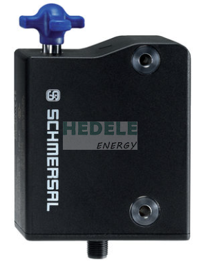
AZM300Z-I2-ST-1P2P-DU
Delivery time:14-16 weeks
| Standards |
EN ISO 13849-1 EN ISO 14119 EN IEC 60947-5-3 EN IEC 61508 |
| Coding |
Individual coding, multiple teaching |
| Coding level according to EN ISO 14119 |
High |
| Working principle |
RFID |
| Frequency band RFID |
125 kHz |
| Transmitter output RFID, maximum |
-6 dB/m |
| Enclosure material |
Plastic, glass-fibre reinforced thermoplastic, self-extinguishing |
| Gross weight |
550 g |
| Duration of risk, maximum |
200 ms |
| Reaction time, switching off safety outputs via actuator, maximum |
100 ms |
| Reaction time, switching off safety outputs via safety inputs, maximum |
1.5 ms |
| Power to unlock |
Yes |
| Solenoid interlock monitored |
Yes |
| Latching |
Yes |
| Manual release |
Yes |
| Short circuit detection |
Yes |
| Cross-circuit detection |
Yes |
| Series-wiring |
Yes |
| Safety functions |
Yes |
| Integral system diagnostics, status |
Yes |
| Number of actuating directions |
3 |
| Number of fail-safe digital outputs |
2 |
| Safety classification |
| Standards |
EN ISO 13849-1 EN IEC 61508 |
| Performance Level, up to |
e |
| Category |
4 |
| PFH value |
5.20 x 10⁻¹⁰ /h |
| PFD value |
4.50 x 10⁻⁵ |
| Safety Integrity Level (SIL), suitable for applications in |
3 |
| Mission time |
20 Year(s) |
| Performance Level, up to |
d |
| Category |
2 |
| PFH value |
2.00 x 10⁻⁹ /h |
| PFD value |
1.80 x 10⁻⁴ |
| Safety Integrity Level (SIL), suitable for applications in |
2 |
| Mission time |
20 Year(s) |
| Mechanical life, minimum |
1,000,000 Operations |
| Note (Mechanical life) |
When using as door stop: ≥ 50.000 operations (door mass ≤ 5 kg and actuating speed ≤ 0.5 m/s) |
| Angular misalignment between solenoid interlock and actuator, maximum |
2 ° |
| Holding force FZh in accordance with EN ISO 14119 |
1,150 N |
| Holding force Fmax, maximum |
1,500 N |
| Latching force, adjustable, position 1 |
25 N |
| Latching force, adjustable, position 2 |
50 N |
| Type of the fixing screws |
2x M6 |
| Tightening torque of the fixing screws, minimum |
6 Nm |
| Tightening torque of the fixing screws, maximum |
7 Nm |
| Switch distance, typical |
2 mm |
| Assured switching distance "ON" Sao |
1 mm |
| Assured switching distance "OFF" Sar |
20 mm |
| Termination |
Connector M12, 8-pole, A-coded |
| Length of sensor chain, maximum |
200 m |
| Note (length of the sensor chain) |
Cable length and cross-section change the voltage drop dependiing on the output current |
| Note (series-wiring) |
Unlimited number of devices, oberserve external line fusing, max. 31 devices in case of serial diagnostic SD |
| Length of sensor |
120 mm |
| Width of sensor |
87.5 mm |
| Height of sensor |
35 mm |
| Degree of protection |
IP67 IP69 IP66 |
| Ambient temperature |
+0 ... +60 °C |
| Storage and transport temperature, minimum |
-10 °C |
| Storage and transport temperature, maximum |
+90 °C |
| Relative humidity, maximum |
93 % |
| Note (Relative humidity) |
non-condensing non-icing |
| Resistance to vibrations |
10 … 150 Hz, amplitude 0.35 mm |
| Restistance to shock |
30 g / 11 ms |
| Protection class |
III |
| Permissible installation altitude above sea level, maximum |
2,000 m |
| Rated insulation voltage Ui |
32 VDC |
| Rated impulse withstand voltage Uimp |
0.8 kV |
| Overvoltage category |
III |
| Degree of pollution |
3 |
| Operating voltage |
24 VDC -15 % / +10 % (stabilised PELV power supply) |
| No-load supply current I0, maximum |
100 mA |
| Current consumption with magnet ON, average |
200 mA |
| Current consumption with magnet ON, peak |
350 mA / 200 ms |
| Rated operating voltage |
24 VDC |
| Required rated short-circuit current |
100 A |
| External wire and device fuse rating |
2 A gG |
| Time to readiness, maximum |
5,000 ms |
| Switching frequency, maximum |
0.5 Hz |
| Designation, Magnet control |
IN |
| Switching thresholds |
-3 V … 5 V (Low) 15 V … 30 V (High) |
| Current consumption at 24V |
10 mA |
| Magnet switch-on time |
100 % |
| Test pulse duration, maximum |
5 ms |
| Test pulse interval, minimum |
40 ms |
| Classification ZVEI CB24I, Sink |
C0 |
| Classification ZVEI CB24I, Source |
C1 C2 C3 |
| Designation, Safety inputs |
X1 and X2 |
| Switching thresholds |
−3 V … 5 V (Low) 15 V … 30 V (High) |
| Current consumption at 24V |
5 mA |
| Test pulse duration, maximum |
1 ms |
| Test pulse interval, minimum |
100 ms |
| Classification ZVEI CB24I, Sink |
C1 |
| Classification ZVEI CB24I, Source |
C1 C2 C3 |
| Designation, Safety outputs |
Y1 and Y2 |
| Design of control elements |
short-circuit proof, p-type |
| Voltage drop Ud, maximum |
2 V |
| Leakage current Ir, maximum |
0.5 mA |
| Voltage, Utilisation category DC-12 |
24 VDC |
| Current, Utilisation category DC-12 |
0.25 A |
| Voltage, Utilisation category DC-13 |
24 VDC |
| Current, Utilisation category DC-13 |
0.25 A |
| Test pulse interval, typical |
1000 ms |
| Test pulse duration, maximum |
0.5 ms |
| Classification ZVEI CB24I, Source |
C2 |
| Classification ZVEI CB24I, Sink |
C1 C2 |
| Designation, Diagnostic outputs |
OUT |
| Voltage drop Ud, maximum |
2 V |
| Voltage, Utilisation category DC-12 |
24 VDC |
| Current, Utilisation category DC-12 |
0.05 A |
| Voltage, Utilisation category DC-13 |
24 VDC |
| Current, Utilisation category DC-13 |
0.05 A |
| Note (LED switching conditions display) |
Operating condition: LED green Error / functional defect: LED red Supply voltage UB: LED green |
| PIN 1 |
A1 Supply voltage UB |
| PIN 2 |
X1 Safety input 1 |
| PIN 3 |
A2 GND |
| PIN 4 |
Y1 Safety output 1 |
| PIN 5 |
OUT Diagnostic output |
| PIN 6 |
X2 Safety input 2 |
| PIN 7 |
Y2 Safety output 2 |
| PIN 8 |
IN Solenoid control |
| Scope of delivery |
Actuator must be ordered separately. |
| Recommendation (actuator) |
AZ/AZM300-B1 |
| Note (General) |
For doors that are flush with the door frame, the optional mounting plate MP-AZ/AZM300-1 can be used. For glass and Makrolon doors, the optional mounting kit MS-AZ/AZM300-B1-1 can be used. As long as the actuating unit remains inserted in the solenoid interlock, the unlocked safety guard can be relocked. In this case, the safety outputs are re-enabled, so that the safety guard must not be opened. |