HJY
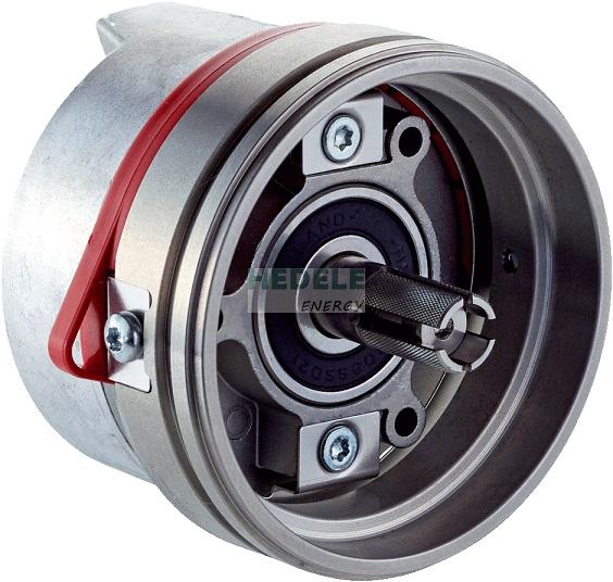
SRM50-HZZ0-S21
Delivery time: spot goods
| Special device | ✔ |
| Sine/cosine periods per revolution | 1,024 |
| Number of the absolute ascertainable revolutions | 1 |
| Total number of steps | 32,768 |
| Measuring step | 0.3 ″ For interpolation of the sine/cosine signals with, e. g., 12 bits |
| Integral non-linearity | Typ. ± 45 ″, Error limits for evaluating sine/cosine period, without mechanical tension of the stator coupling |
| Differential non-linearity | ± 7 ″, Non-linearity within a sine/cosine period |
| Operating speed | ≤ 6,000 min⁻¹, up to which the absolute position can be reliably produced |
| Available memory area | 128 Byte |
| System accuracy | ± 52 ″ |
| Type of code for the absolute value | Binary |
| Code sequence | Increasing, when turning the shaft For clockwise rotation, looking in direction “A” (see dimensional drawing), For clockwise shaft rotation, looking in direction “A” (see dimensional drawing) |
| Communication interface | HIPERFACE® |
| Connection type | Male connector, 8-pin, radial |
| Supply voltage | 7 V DC ... 12 V DC |
| Recommended supply voltage | 8 V DC |
| Power consumption | 80 mA 1) |
| Output frequency for sine/cosine signals | ≤ 200 kHz |
| MTTF: mean time to dangerous failure | 235 years (EN ISO 13849) 2) |
| Shaft version | Expanding shaft with slot for form-fitting |
| Flange type / stator coupling | Spring mounting plate |
| Dimensions | See dimensional drawing |
| Weight | ≤ 0.2 kg |
| Moment of inertia of the rotor | 10 gcm² |
| Operating speed | ≤ 12,000 min⁻¹ |
| Angular acceleration | ≤ 200,000 rad/s² |
| Operating torque | 0.2 Ncm |
| Start up torque | + 0.4 Ncm |
| Permissible movement of the drive element, static |
± 0.3 mm radial ± 0.75 mm axial |
| Permissible movement of the drive element, dynamic |
± 0.1 mm radial ± 0.2 mm axial |
| Angular motion perpendicular to the rotational axis, static | ± 0.005 mm/mm |
| Angular motion perpendicular to the rotational axis, dynamic | ± 0.0025 mm/mm |
| Life of ball bearings | 3.6 x 10⁹ revolutions |
| Operating temperature range | –30 °C ... +115 °C |
| Storage temperature range | –40 °C ... +125 °C, without package |
| Relative humidity/condensation | 90 %, Condensation not permitted |
| Resistance to shocks | 100 g, 10 ms, 10 ms (according to EN 60068-2-27) |
| Frequency range of resistance to vibrations | 20 g, 10 Hz ... 2,000 Hz (EN 60068-2-6) |
| EMC | According to EN 61000-6-2 and EN 61000-6-3 1) |
| Enclosure rating | IP40, with mating connector inserted (IEC 60529) |