HCM
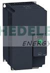
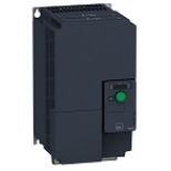
ATV320D15M3C
Delivery time:1 month
Specifications
| Range of Product | Altivar Machine ATV320 |
|---|---|
| Product or Component Type | Variable speed drive |
| Product Specific Application | Complex machines |
| variant | Standard version |
| Format of the drive | Compact |
| Mounting Mode | Wall mount |
| Communication Port Protocol |
Modbus serial CANopen |
| Option card |
Communication module, CANopen communication module, EtherCAT communication module, Profibus DP V1 communication module, PROFINET communication module, Ethernet Powerlink communication module, EtherNet/IP communication module, DeviceNet |
| [Us] rated supply voltage | 200...240 V - 15...10 % |
| Nominal output current | 66.0 A |
| Motor power kW | 15.0 kW heavy duty |
| EMC filter | Without EMC filter |
| IP degree of protection | IP20 |
| Discrete input number | 7 |
|---|---|
| Discrete input type |
STO safe torque off, 24 V DC1.5 kOhm DI1...DI6 logic inputs, 24 V DC 30 V) DI5 programmable as pulse input 0…30 kHz, 24 V DC 30 V) |
| Discrete input logic |
Positive logic (source) Negative logic (sink) |
| Discrete output number | 3 |
| Discrete output type |
Open collector DQ+ 0…1 kHz 30 V DC 100 mA Open collector DQ- 0…1 kHz 30 V DC 100 mA |
| Analogue input number | 3 |
| Analogue input type |
AI1 voltage 0...10 V DC 30 kOhm 10 bits AI2 bipolar differential voltage +/- 10 V DC 30 kOhm 10 bits AI3 current 0...20 mA (or 4-20 mA, x-20 mA, 20-x mA or other patterns by configuration) 250 Ohm 10 bits |
| Analogue output number | 1 |
| Analogue output type |
Software-configurable current AQ1 0...20 mA 800 Ohm 10 bits Software-configurable voltage AQ1 0...10 V DC 470 Ohm 10 bits |
| Relay output type |
Configurable relay logic R1A 1 NO 100000 cycles Configurable relay logic R1B 1 NC 100000 cycles Configurable relay logic R1C Configurable relay logic R2A 1 NO 100000 cycles Configurable relay logic R2C |
| Maximum switching current |
Relay output R1A, R1B, R1C resistive, cos phi = 1 3 A 250 V AC Relay output R1A, R1B, R1C resistive, cos phi = 1 3 A 30 V DC Relay output R1A, R1B, R1C, R2A, R2C inductive, cos phi = 0.4 7 ms 2 A 250 V AC Relay output R1A, R1B, R1C, R2A, R2C inductive, cos phi = 0.4 7 ms 2 A 30 V DC Relay output R2A, R2C resistive, cos phi = 1 5 A 250 V AC Relay output R2A, R2C resistive, cos phi = 1 5 A 30 V DC |
| Minimum switching current | Relay output R1A, R1B, R1C, R2A, R2C 5 mA 24 V DC |
| Method of access | Slave CANopen |
| 4 quadrant operation possible | True |
| Asynchronous motor control profile |
Voltage/frequency ratio, 5 points Flux vector control without sensor, standard Voltage/frequency ratio - Energy Saving, quadratic U/f Flux vector control without sensor - Energy Saving Voltage/frequency ratio, 2 points |
| Synchronous motor control profile | Vector control without sensor |
| Maximum output frequency | 0.599 kHz |
| Transient overtorque | 170…200 % of nominal motor torque |
| Acceleration and deceleration ramps |
Linear U S CUS Ramp switching Acceleration/deceleration ramp adaptation Acceleration/deceleration automatic stop with DC injection |
| Motor slip compensation |
Automatic whatever the load Adjustable 0...300 % Not available in voltage/frequency ratio (2 or 5 points) |
| Switching frequency |
2...16 kHz adjustable 4...16 kHz with derating factor |
| Nominal switching frequency | 4 kHz |
| Braking to standstill | By DC injection |
| Brake chopper integrated | True |
| Line current |
79.7 A 200 V heavy duty) 67.1 A 240 V heavy duty) |
| Maximum Input Current per Phase | 79.7 A |
| Maximum output voltage | 240 V |
| Apparent power | 27.9 kVA 240 V heavy duty) |
| Network Frequency | 50-60 Hz |
| Relative symmetric network frequency tolerance | 5 % |
| Prospective line Isc | 22 kA |
| Base load current at high overload | 8.0 A |
| Power dissipation in W | Fan 551 W 200 V 4 kHz |
| With safety function Safely Limited Speed (SLS) | True |
| With safety function Safe brake management (SBC/SBT) | False |
| With safety function Safe Operating Stop (SOS) | False |
| With safety function Safe Position (SP) | False |
| With safety function Safe programmable logic | False |
| With safety function Safe Speed Monitor (SSM) | False |
| With safety function Safe Stop 1 (SS1) | True |
| With sft fct Safe Stop 2 (SS2) | False |
| With safety function Safe torque off (STO) | True |
| With safety function Safely Limited Position (SLP) | False |
| With safety function Safe Direction (SDI) | False |