HCM(YMX)
IB IL 24 PSDI 8-PAC-2985688
Delivery time:4-5 months
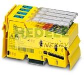
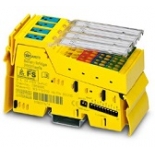
| Dimensional drawing |
|
| Width | 48.8 mm |
| Height | 119.8 mm |
| Depth | 71.5 mm |
| Note on dimensions | Housing dimensions |
| Inline local bus | |
| No. of channels | 2 |
| Connection method | Inline data jumper |
| Transmission speed | 500 kbps / 2 Mbps (can be switched) |
| Module | |
| ID code (dec.) | 163 |
| ID code (hex) | A3 |
| Length code (hex) | 04 |
| Length code (dec) | 04 |
| Process data channel | 8 Byte |
| Input address area | 8 Byte ((Operating mode: SafetyBridge)) |
| Output address area | 8 Byte ((Operating mode: SafetyBridge)) |
| Register length | 8 Byte |
| Required parameter data | 1 Byte ((Operating mode: SafetyBridge)) |
| Required configuration data | 5 Byte ((Operating mode: SafetyBridge)) |
| Digital | |
| Input name | Digital inputs |
| Description of the input | IEC 61131-2 type 3 |
| Number of inputs | 4 (for 2-channel assignment) |
| 8 (for 1-channel assignment) | |
| Cable length | max. 200 m (200 m from the clock output to the safe input (total based on forward and return path)) |
| Connection method | Spring-cage connection |
| Connection technology | 2-, 3-, 4-conductor |
| Input voltage | 24 V DC (via clock outputs UT1 and UT2 or external supply) |
| Input voltage range | -3 V DC ... 30 V DC |
| Input voltage range "0" signal | -3 V DC ... 5 V DC |
| Input voltage range "1" signal | 11 V DC ... 30 V DC |
| Typical input current per channel | 4.2 mA (at 24 V) |
| Typical response time | See technical data |
| Type | modular |
| Product type | I/O component |
| Product family | Inline |
| Application | Functional safety |
| Maximum power dissipation for nominal condition | 24.12 W |
| Transmission medium | Copper |
| Potentials: Communications power (UL) | |
| Supply voltage | 7.5 V DC (see safety data) |
| Current draw | max. 180 mA |
| Potentials: Main circuit supply (UM) | |
| Supply voltage | 24 V DC |
| Supply voltage range | 19.2 V DC ... 30 V DC (including all tolerances, including ripple) |
| Current draw | max. 825 mA (see safety data) |
| typ. 25 mA (plus current consumption of the inputs when supplied via the clock outputs, plus current consumption of the connected initiators when via through the clock outputs) | |
| Supply: Module electronics | |
| Supply voltage | 24 V DC (via voltage jumper) |
| Supply voltage range | 19.2 V DC ... 30 V DC |
| Connection technology | |
| Connection name | Inline connector |
| pluggable | yes |
| Conductor connection | |
| Connection method | Spring-cage connection |
| Conductor cross section solid | 0.2 mm² ... 1.5 mm² |
| Conductor cross section flexible | 0.2 mm² ... 1.5 mm² |
| Conductor cross section AWG | 24 ... 16 |
| Inline connector | |
| Connection method | Spring-cage connection |
| Conductor cross section, rigid | 0.2 mm² ... 1.5 mm² |
| Conductor cross section, flexible | 0.2 mm² ... 1.5 mm² |
| Conductor cross section AWG | 24 ... 16 |
| Ambient conditions | |
| Ambient temperature (operation) | -25 °C ... 55 °C |
| Degree of protection | IP20 |
| Air pressure (operation) | 80 kPa ... 108 kPa (up to 2000 m above sea level) |
| Air pressure (storage/transport) | 66 kPa ... 108 kPa (up to 3500 m above sea level) |
| Ambient temperature (storage/transport) | -25 °C ... 70 °C |
| Permissible humidity (operation) | 10 % ... 85 % (Take suitable measures against increased air humidity within the permitted temperature range.) |
| Permissible humidity (storage/transport) | 10 % ... 85 % (Take suitable measures against increased air humidity within the permitted temperature range.) |
| Protection class | III (IEC 61140, EN 61140, VDE 0140-1) |
| Mounting type | DIN rail mounting |