HCM(XWY)
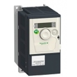
ATV312H018M2
Delivery time:1 week
Range of product
Altivar 312
Product or component type
Variable speed drive
Product destination
Asynchronous motors
Product specific application
Simple machine
Assembly style
With heat sink
Component name
ATV312
Motor power kW
0.18 kW
Motor power hp
0.25 hp
[Us] rated supply voltage
200...240 V - 15...10 %
Supply frequency
50...60 Hz - 5...5 %
Network number of phases
Single phase
Line current
3 A at 200 V, Isc = 5 kA
2.5 A at 240 V
EMC filter
Integrated
Apparent power
0.6 kVA
Maximum transient current
2.3 A for 60 s
Power dissipation in W
24 W at nominal load
Speed range
1…50
Asynchronous motor control profile
Sensorless flux vector control with PWM type motor control signal
Factory set : constant torque
Electrical connection
Al1, Al2, Al3, AOV, AOC, R1A, R1B, R1C, R2A, R2B, LI1...LI6 terminal 2.5 mm² AWG 14
L1, L2, L3, U, V, W, PA, PB, PA/+, PC/- terminal 2.5 mm² AWG 14
Supply
Internal supply for logic inputs: 19...30 V 100 mA, protection type: overload and short-circuit protection
Internal supply for reference potentiometer (2.2 to 10 kOhm): 10...10.8 V 10 mA, protection type: overload and short-circuit protection
Communication port protocol
Modbus
CANopen
IP degree of protection
IP20 on upper part without cover plate
IP21 on connection terminals
IP31 on upper part
IP41 on upper part
Option card
Communication card for CANopen daisy chain
Communication card for DeviceNet
Communication card for Fipio
Communication card for Modbus TCP
Communication card for Profibus DP
Supply voltage limits
170…264 V
Prospective line Isc
5 kA
Continuous output current
1.5 A at 4 kHz
Output frequency
0…500 Hz
Nominal switching frequency
4 kHz
Switching frequency
2...16 kHz adjustable
Transient overtorque
170…200 % of nominal motor torque
Braking torque
150 % during 60 s with braking resistor
100 % with braking resistor continuously
150 % without braking resistor
Regulation loop
Frequency PI regulator
Motor slip compensation
Automatic whatever the load
Suppressable
Adjustable
Output voltage
<= power supply voltage
Tightening torque
Al1, Al2, Al3, AOV, AOC, R1A, R1B, R1C, R2A, R2B, LI1...LI6: 0.6 N.m
L1, L2, L3, U, V, W, PA, PB, PA/+, PC/-: 0.8 N.m
Insulation
Electrical between power and control
Analogue input number
3
Analogue input type
AI1 configurable voltage 0...10 V, input voltage 30 V max, impedance: 30000 Ohm
AI2 configurable voltage +/- 10 V, input voltage 30 V max, impedance: 30000 Ohm
AI3 configurable current 0...20 mA, impedance: 250 Ohm
Sampling duration
AI1, AI2, AI3: 8 ms analog
LI1...LI6: 4 ms discrete
Response time
AOV, AOC 8 ms for analog
R1A, R1B, R1C, R2A, R2B 8 ms for discrete
Linearity error
+/- 0.2 % for output
Analogue output number
1
Analogue output type
AOC configurable current: 0...20 mA, impedance: 800 Ohm, resolution: 8 bits
AOV configurable voltage: 0...10 V, impedance: 470 Ohm, resolution: 8 bits
Discrete input logic
Logic input not wired (LI1...LI4), < 13 V (state 1)
Negative logic (source) (LI1...LI6), > 19 V (state 0)
Positive logic (source) (LI1...LI6), < 5 V (state 0), > 11 V (state 1)
Discrete output number
2
Discrete output type
Configurable relay logic: (R1A, R1B, R1C) 1 NO + 1 NC - 100000 cycles
Configurable relay logic: (R2A, R2B) NC - 100000 cycles
Minimum switching current
R1-R2 10 mA at 5 V DC
Maximum switching current
R1-R2: 2 A at 250 V AC inductive load, cos phi = 0.4 and L/R = 7 ms
R1-R2: 2 A at 30 V DC inductive load, cos phi = 0.4 and L/R = 7 ms
R1-R2: 5 A at 250 V AC resistive load, cos phi = 1 and L/R = 0 ms
R1-R2: 5 A at 30 V DC resistive load, cos phi = 1 and L/R = 0 ms
Discrete input number
6
Discrete input type
(LI1...LI6) programmable at 24 V, 0…100 mA for PLC, impedance: 3500 Ohm
Acceleration and deceleration ramps
Linear adjustable separately from 0.1 to 999.9 s
S, U or customized
Braking to standstill
By DC injection
Protection type
Input phase breaks: drive
Line supply overvoltage and undervoltage safety circuits: drive
Line supply phase loss safety function, for three phases supply: drive
Motor phase breaks: drive
Overcurrent between output phases and earth (on power up only): drive
Overheating protection: drive
Short-circuit between motor phases: drive
Thermal protection: motor
Insulation resistance
>= 500 mOhm 500 V DC for 1 minute
Local signalling
1 LED (red) for drive voltage
Four 7-segment display units for CANopen bus status
Time constant
5 ms for reference change
Frequency resolution
Analog input: 0.1...100 Hz
Display unit: 0.1 Hz
Connector type
1 RJ45 for Modbus/CANopen
Physical interface
RS485 multidrop serial link
Transmission frame
RTU
Transmission rate
10, 20, 50, 125, 250, 500 kbps or 1 Mbps for CANopen
4800, 9600 or 19200 bps for Modbus
Number of addresses
1…127 for CANopen
1…247 for Modbus
Number of drive
127 for CANopen
31 for Modbus
Marking
CE
operating position
Vertical +/- 10 degree
Height
145 mm
Width
72 mm
Depth
132 mm
Net weight
1.5 kg