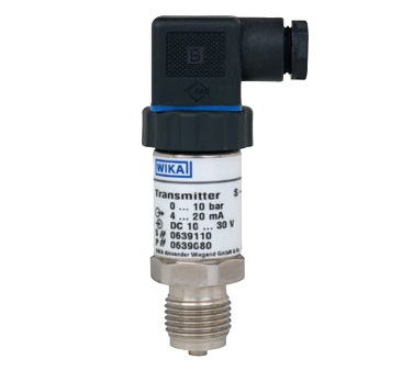
S-10 Wika Pressure Transmitter
delivery time:6 weeks
Applications
bar
Measuring range
0 ... 0.1
0 ... 0.16
0 ... 0.25
0 ... 0.4
0 ... 0.6
0 ... 1
0 ... 1.6
Overload safety
1
1.5
2
2
4
5
10
Measuring range
0 ... 2.5
0 ... 4
0 ... 6
0 ... 10
0 ... 16
0 ... 25
0 ... 40
Overload safety
10
17
35
35
80
50
80
Measuring range
0 ... 60
0 ... 100
0 ... 160
0 ... 250
0 ... 400
0 ... 600
0 ... 1,000
Overload safety
120
200
320
500
800
1,200
1,500
psi
Measuring range
0 ... 5
0 ... 10
0 ... 15
0 ... 20
0 ... 25
0 ... 30
0 ... 50
Overload safety
29
29
72.5
145
145
145
240
Measuring range
0 ... 60
0 ... 100
0 ... 150
0 ... 160
0 ... 170
0 ... 200
0 ... 250
Overload safety
240
500
500
1,160
1,160
1,160
1,160
Measuring range
0 ... 300
0 ... 400
0 ... 500
0 ... 600
0 ... 750
0 ... 800
0 ... 1,000
Overload safety
1,160
1,160
1,160
1,160
1,740
1,740
1,740
Measuring range
0 ... 1,500
0 ... 1,600
0 ... 2,000
0 ... 3,000
0 ... 4,000
0 ... 5,000
0 ... 6,000
Overload safety
2,900
4,600
4,600
7,200
7,200
11,600
11,600
Measuring range
0 ... 7,500
0 ... 8,000
0 ... 10,000
0 ... 15,000
Overload safety
17,400
17,400
17,400
21,700
bar
Measuring range
0 ... 0.25
0 ... 0.4
0 ... 0.6
0 ... 1
0 ... 1.6
0 ... 2.5
0 ... 4
Overload safety
2
2
4
5
10
10
17
Measuring range
0 ... 6
0 ... 10
0 ... 16
0 ... 25
0.8 ... 1.2
Overload safety
35
35
80
80
5
psi
Measuring range
0 ... 15
0 ... 25
0 ... 50
0 ... 100
0 ... 250
Overload safety
72.5
145
240
500
1,160
Vacuum and +/- measuring range
bar
Measuring range
-0.6 ... 0
-0.4 ... 0
-0.25 ... 0
-0.16 ... 0
-0.1 ... 0
Overload safety
4
2
2
1.5
1
Measuring range
-1 ... 0
-1 ... +0.6
-1 ... +1.5
-1 ... +3
-1 ... +5
Overload safety
5
10
10
17
35
Measuring range
-1 ... +9
-1 ... +15
-1 ... +24
Overload safety
35
80
50
psi
Measuring range
-15 inHg ... 0
-30 inHg ... 0
-30 inHg ... +15
-30 inHg ... +30
-30 inHg ... +60
Overload safety
72.5
72.5
145
240
240
Measuring range
-30 inHg ... +100
-30 inHg ... +160
-30 inHg ... +200
-30 inHg ... +300
Overload safety
500
1,160
1,160
1,160
Signal type
Signal
Current (2-wire)
4 ... 20 mA
20 ... 4 mA
Current (3-wire)
0 ... 20 mA
Voltage (3-wire)
DC 0 ... 10 V
DC 0 ... 5 V
DC 1 ... 5 V
DC 0.5 ... 4.5 V ratiometric
Standard
≤ ±0.50 % of span
Option
≤ ±0.25 % of span 1)
Standard
Option
Medium
-30 ... +100 °C [-22 ... +212 °F]
-40 ... +125 °C [-40 ... +257 °F]
Ambient
-20 ... +80 °C [-4 ... +176 °F]
-20 ... +80 °C [-4 ... +176 °F]
Storage
-40 ... +100 °C [-40 ... +212 °F]
-40 ... +100 °C [-40 ... +212 °F]
Standard
Thread size
EN 837
G ¼ B
G ½ B
DIN EN ISO 1179-2 (formerly DIN 3852-E)
G ¼ A 1)
-
G ¼ female
ANSI/ASME B1.20.1
¼ NPT
½ NPT
SAE J514 E
7/16-20 UNF with 74° taper
-
M20 x 1.5
-
G ½ male / G ¼ female
ISO 7
R ¼
2-wire
3-wire
U+
1
1
U-
2
2
S+
-
3
2-wire
3-wire
U+
1
1
U-
2
2
S+
-
3
2-wire
3-wire
U+
1
1
U-
3
3
S+
-
4
2-wire
3-wire
U+
A
A
U-
B
B
S+
-
C
2-wire
3-wire
U+
red (RD)
red (RD)
U-
black (BK)
black (BK)
S+
-
brown (BN)
2-wire
3-wire
U+
brown (BN)
brown (BN)
U-
green (GN)
green (GN)
S+
-
white (WH)
Shield
grey (GY)
grey (GY)
Electrical connection
Ingress
Wire cross-section
Cable
Cable lengths
Angular connector DIN 175301-803 A
IP65
max. 1.5 mm2
6 ... 8 mm
-
Angular connector DIN 175301-803 with ½ NPT
IP65
max. 1.5 mm2
-
-
Circular connector M12 x 1 (4-pin)
IP67
-
-
-
Bayonet connector (6-pin)
IP67
-
-
-
½ NPT conduit male, with cable outlet
IP67
3 x 0.5 mm2
6.8 mm
1.5 m, 3 m, 5 m, 10 m, 5 ft,
Cable outlet
■ Standard
IP67
3 x 0.5 mm2
6.8 mm
1.5 m, 3 m, 5 m, 10 m, 5 ft,
■ not adjustable
IP68 1)
3 x 0.5 mm2
6.8 mm
■ adjustable
IP68 1)
3 x 0.5 mm2
6.8 mm
■ Machine building
■ Hydraulics and pneumatics
■ Pumps
■ Chemical industry
Special features
■ Measuring ranges from 0 ... 0.1 to 0 ... 1,000 bar [0 ... 5 psi
to 0 ... 15,000 psi]
■ Non-linearity 0.2 % of span (BFSL)
■ Output signals: 4 ... 20 mA, DC 0 ... 10 V, DC 0 ... 5 V and
others
■ Electrical connections: Angular connector form A, circular
connector M12 x 1, various cable outlets and others
Pressure transmitter model S-10
WIKA data sheet PE 81.01 ∙ 09/2018 Page 2 of 9
Measuring ranges
Gauge pressure
Absolute pressure
The given measuring ranges are also available in kg/cm2 and MPa.
Other measuring ranges available on request.
Vacuum tightness
Yes
WIKA data sheet PE 81.01 ∙ 09/2018 Page 3 of 9
Output signals
Other output signals on request.
Load in Ω
■ Current output (2-wire):
≤ (power supply - 10 V) / 0.02 A
■ Current output (3-wire):
≤ (power supply - 3 V) / 0.02 A
■ Voltage output (3-wire):
> maximum output signal / 1 mA
Voltage supply
Power supply
The power supply depends on the selected output signal
■ 4 ... 20 mA: DC 10 ... 30 V
■ 20 ... 4 mA: DC 10 ... 30 V
■ 0 ... 20 mA: DC 10 ... 30 V
■ DC 0 ... 5 V: DC 10 ... 30 V
■ DC 1 ... 5 V: DC 10 ... 30 V
■ DC 0 ... 10 V: DC 14 ... 30 V
■ DC 0.5 ... 4.5 V ratiometric: DC 4.5 ... 5.5 V
Reference conditions (per IEC 61298-1)
Temperature
15 ... 25 °C [59 ... 77 °F]
Atmospheric pressure
860 ... 1,060 mbar [86 … 106 kPa/12.5 … 15.4 psig]
Humidity
45 ... 75 % r. h.
Power supply
DC 24 V
Mounting position
Calibrated in vertical mounting position with pressure
connection facing downwards.
Accuracy specifcations
Non-linearity (per IEC 61298-2)
≤ ±0.2 % of span BFSL
Non-repeatability (per IEC 61298-2)
≤ 0.1 % of span
Accuracy at reference conditions
Including non-linearity, hysteresis, zero offset and end value
deviation (corresponds to measured error per IEC 61298-2).
Accuracy
1) Only for measuring ranges ≥ 0.25 bar [≥ 3.6 psi]
Adjustability of zero point and span
Adjustment is made using potentiometers inside the
instrument.
■ Zero point: ± 5 %
■ Span: ± 5 %
Temperature error at 0 ... 80 °C [32 ... 176 °F]
■ Mean temperature coefcient of zero point:
Measuring ranges ≤ 0.25 bar [≤ 3.6 psi]: ≤ 0.4 % of span/10 K
Measuring ranges > 0.25 bar [> 3.6 psi]: ≤ 0.2 % of span/10 K
■ Mean temperature coefcient of span:
≤ 0.2 % of span/10 K
Long-term stability at reference conditions
≤ ±0.2 % of span/year
Time response
Settling time
■ ≤ 1 ms
■ ≤ 2 ms for output signal DC 0.5…4.5 V ratiometric and
measuring ranges < 0.4 bar [< 5.8 psi]
WIKA data sheet PE 81.01 ∙ 09/2018 Page 4 of 9
Operating conditions
Ingress protection (per IEC 60529)
For ingress protections see “Electrical connections”
The stated ingress protection only applies when plugged in using mating
connectors that have the appropriate ingress
protection
Vibration resistance (per IEC 60068-2-6)
20 g
Shock resistance (per IEC 60068-2-27)
1,000 g (mechanical)
Permissible temperature ranges
Process connections
1) Maximum overload safety 600 bar [8,700 psi]
Other process connections on request
Materials
Wetted parts
Measuring ranges ≤ 25 bar [≤ 400 psi]: 316Ti
Measuring ranges > 25 bar [> 400 psi]: 316Ti and S13800
Non-wetted parts
■ Case: 316Ti
■ Internal pressure transmission medium:
Measuring ranges ≤ 25 bar [≤ 400 psi]: synthetic oil
Measuring ranges > 25 bar [> 400 psi]: dry measuring cell
■ Clamping nut: PA
■ Angular connector: PA
■ O-rings at the clamping nut: NBR
■ Flat gasket: VMQ
WIKA data sheet PE 81.01 ∙ 09/2018 Page 5 of 9
Angular connector DIN 175301-803 A
Angular connector DIN 175301-803 A with ½NPT
Circular connector M12 x 1 (4-pin)
Bayonet connector (6-pin)
½ NPT conduit male, with cable outlet
Cable outlets
Electrical connections
protection
diameter
10 ft, 20 ft, 30 ft, others on
request
10 ft, 20 ft, 30 ft, others on
request